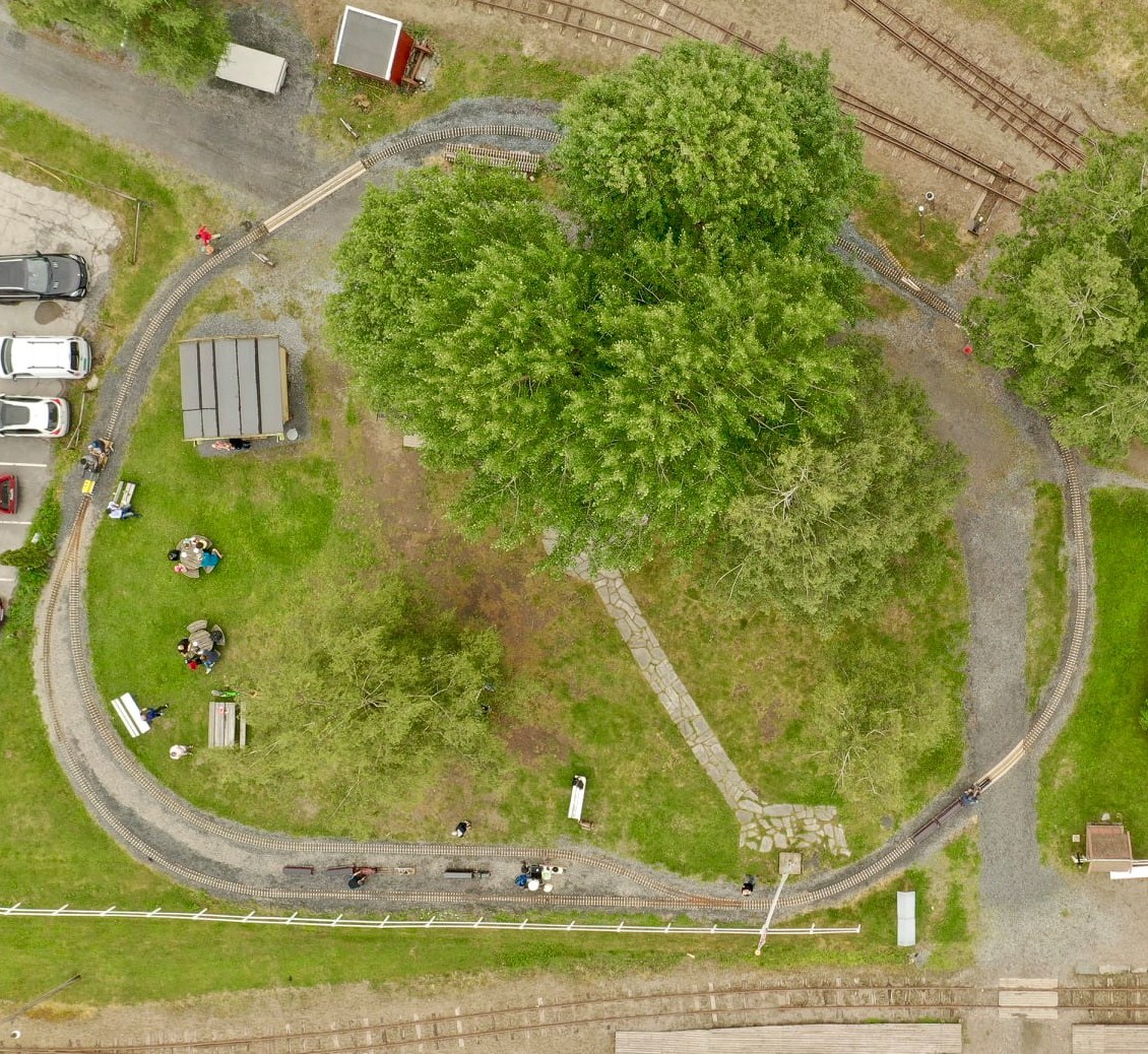
Bird's eye view of miniature railway "Stomperudbanen" in 2021 (photo Åge Westgårdsrønningen)
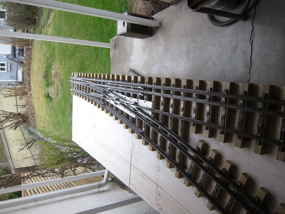
There is a helpful guide on constructing points for a miniature railway: "How to build your own 7¼ ' Gauge Points from Bar Stock," by Colin Edmondsen, from 2012. Additional complications are introduced in the present case through the use of I-section rail rather than bar stock, and by including three rails to allow for two gauge widths. We took over a long work table from Antony and located it on the terrace, just barely big enough, behind my house.
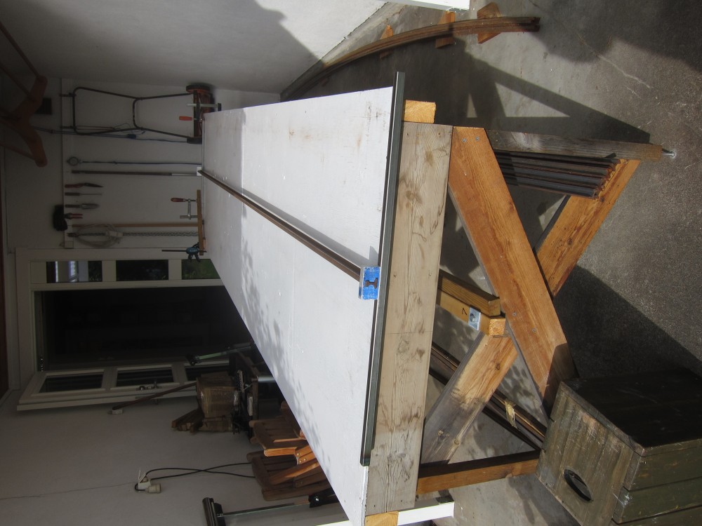
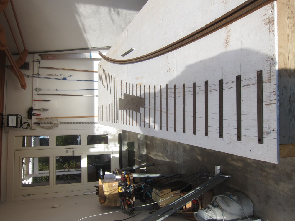
The table has just received a fresh coat of white paint, ready for marking out the points. The table legs have been cross-braced and had M8 studding inserted in the ends, through knock-in nuts, to allow the table to be levelled off.
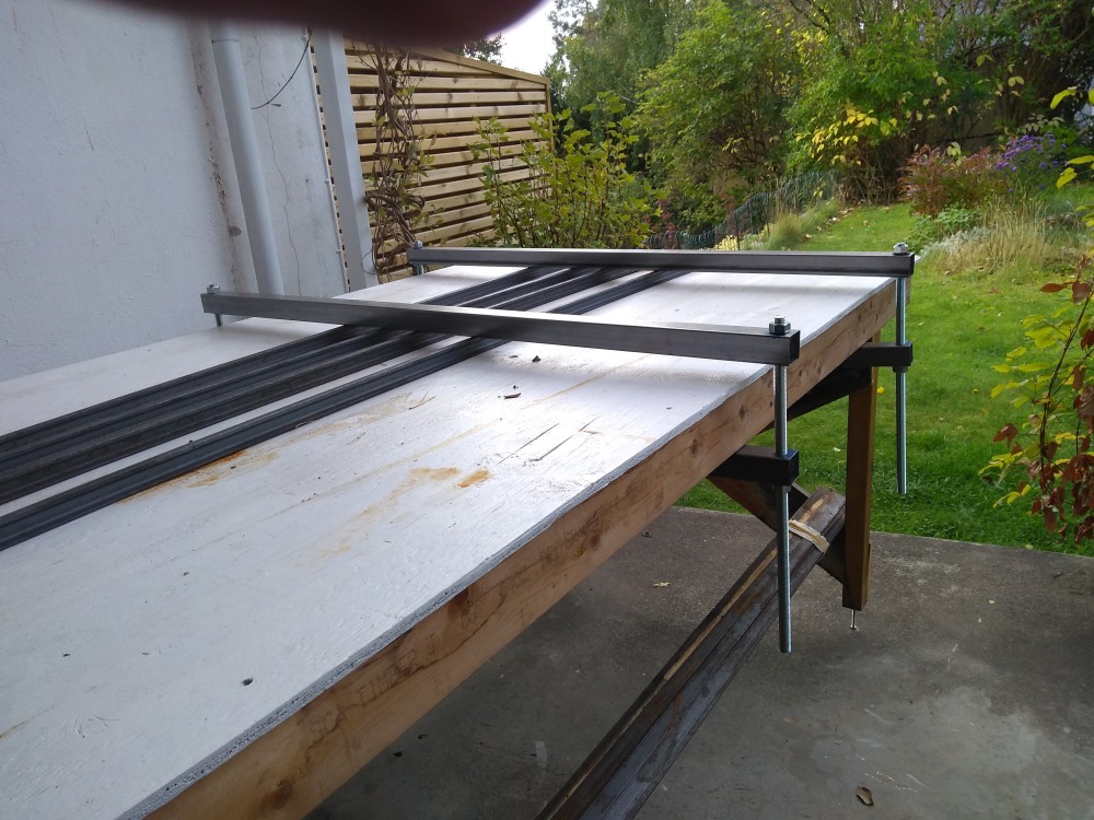
The twisting tool on the table is to remove any twist (about a longitudinal axis through the rail cross-section) that may be present in straight rails. The tool comprises two units of an aluminium block with a hole to fit the rail cross-section, with the block bolted to a metre long piece of 20 mm square steel tube. The first unit is clamped to the far end of the table, with a 4m length of rail inserted in that hole. The other end of the rail projects slightly beyond the near end of the table, such that the second unit may be slipped over the end of the rail, and used to manually untwist the rail. The end of the rail can then be rested on a knife edge and any remaining twist in the rail be assessed.
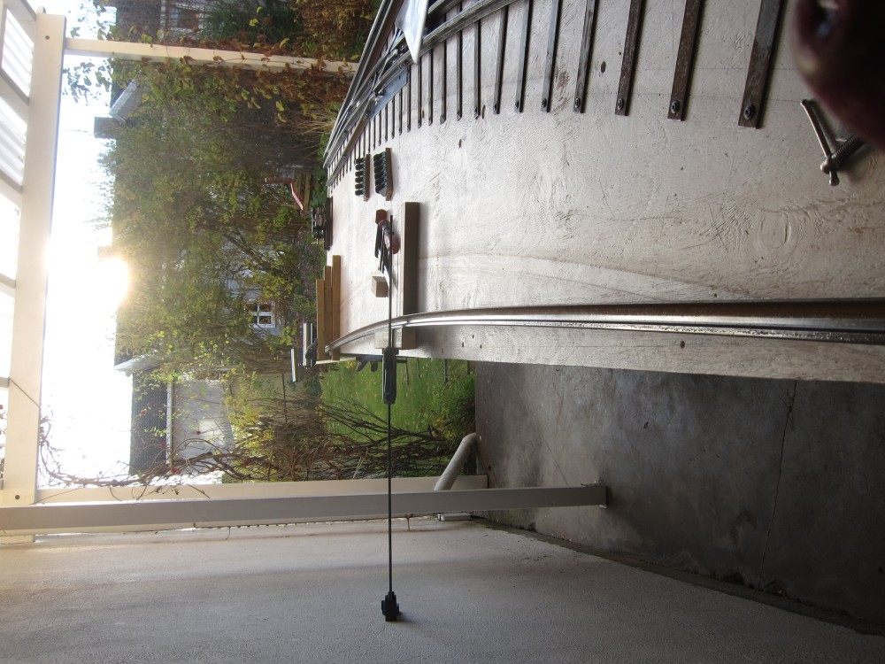
Sometimes otherwise straight rail arrives bowed; i.e. slightly bent around a horizontal axis, such that the mid-point of a length of rail does not rest down on the level work top when the ends do. The photo above shows an arrangement intended to "unbow" such rails. The rail cross-section is relatively resistant to bending about this axis and a little more force was needed than provided by this arrangement. A pair of "persuaders" were assembled from 40mm square steel tube and 14mm studding to force bowed rail down, when necessary; e.g. during welding to steel sleepers. Sometimes it was necessary to add support under the table, to prevent the table top from bending down under the action of the "persuaders."
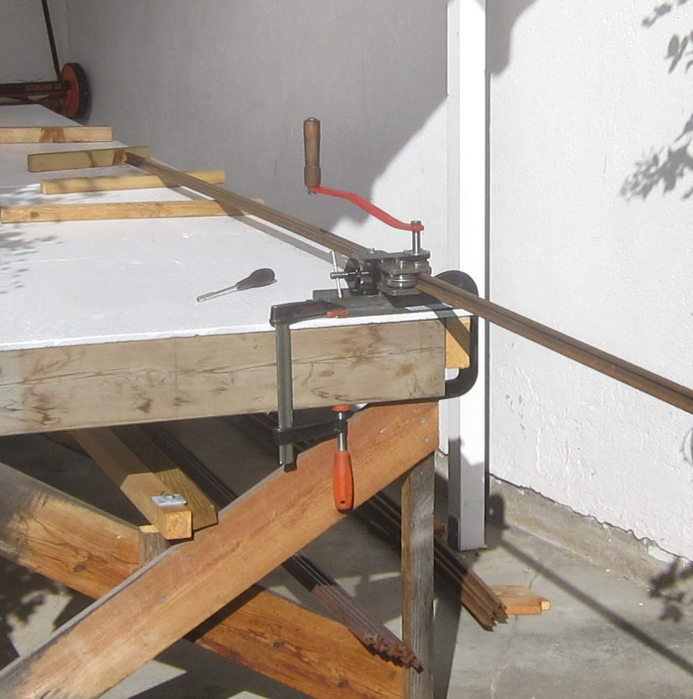
It's not just a question of straightening rails, curved rails are also needed for the points; i.e. rails that are correctly bent. Antony had developed a tool for that purpose (in the photo above), which worked very well. The three rollers in the tool were machined to fit the full profile of the rail. A straight rail was introduced into the tool and cranked back and forth over the full length of the rail, while gradually increasing the curvature. The curvature was checked against a template with the required 10m radius. If the process overshot slightly, then the tool could be used to reduce the curvature, too. While using the tool, it was important to support the weight of the free ends of the rail, to avoid unintended bending. The "curving" of the rail involves bending about a vertical axis through the rail cross-section; there is less resistance to bending about this axis than about the transverse axis mentioned above w.r.t. bowed rail.
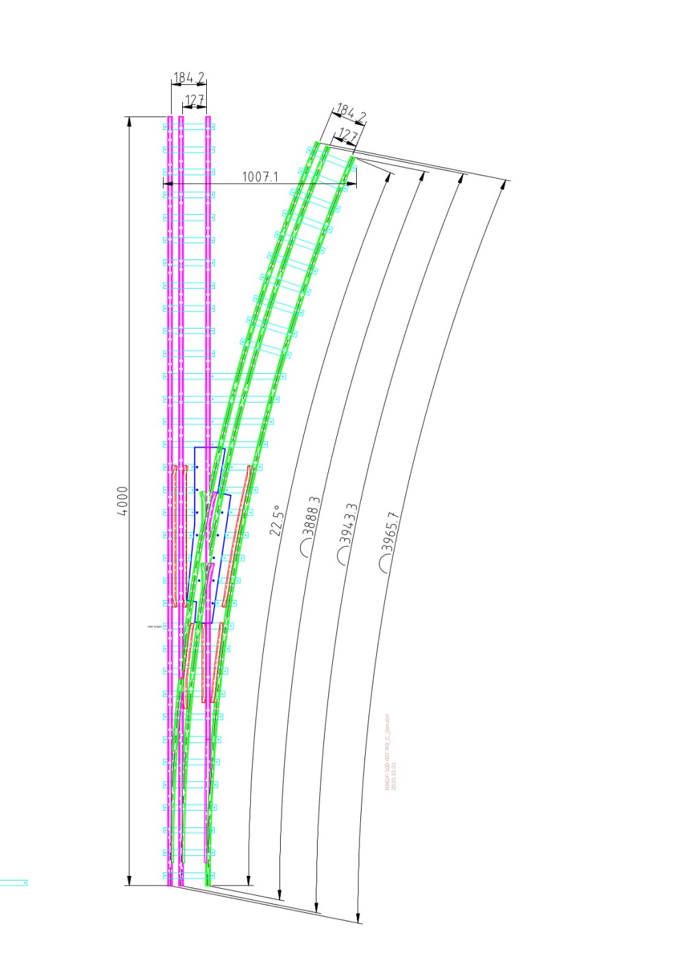
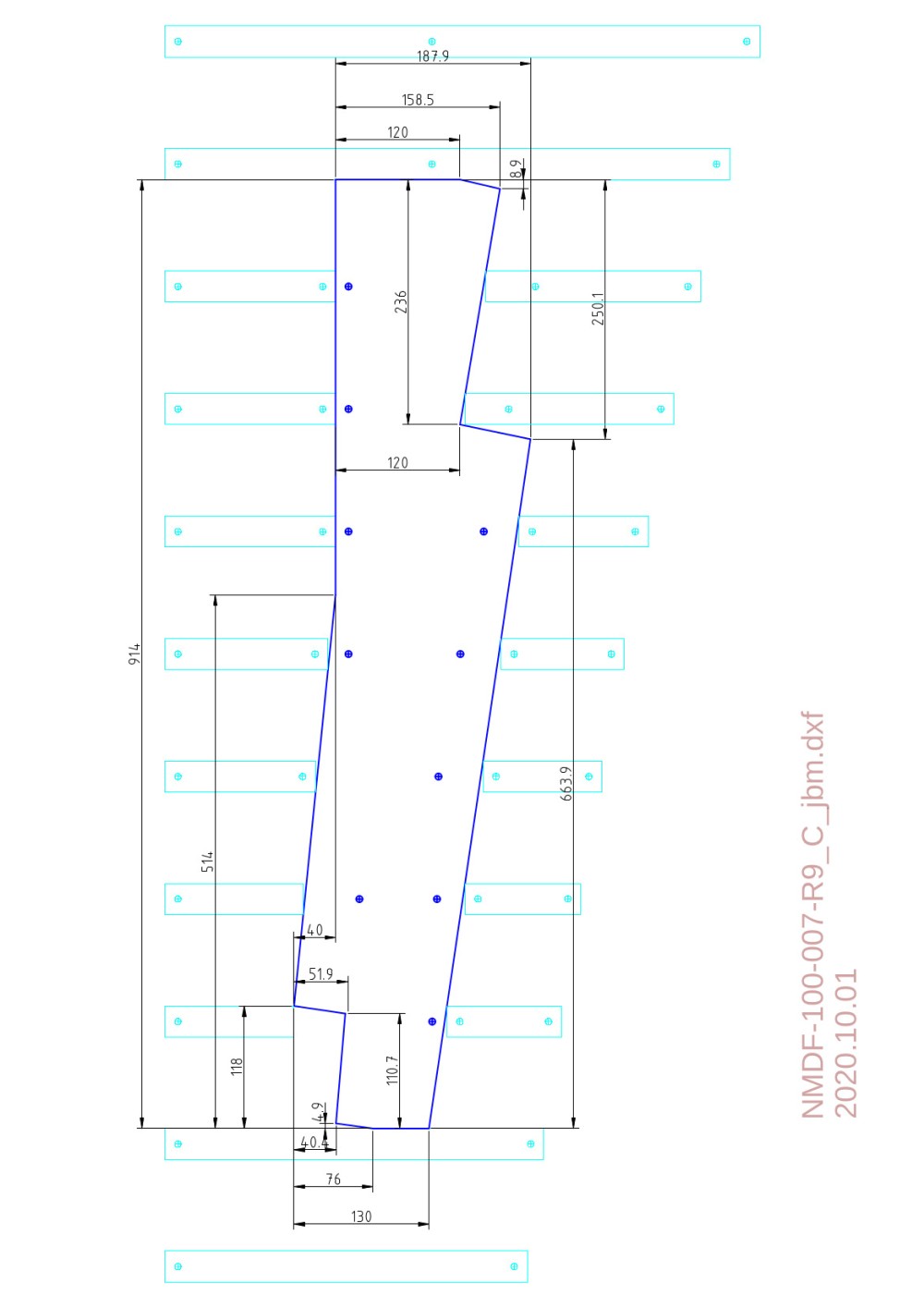
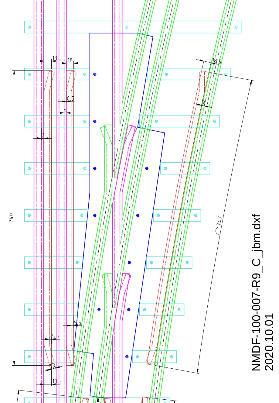
A good deal of effort went into making working drawings of the points. A 2-D drawing program, "QCAD", was used. The drawing process starts with a plan view of 3 parallel rails and 3 curved rails, located as in a set of points. The centrelines of all the rails were drawn first; the centrelines are in the same place, irrespective of the height of the plan-section above the base level, which was taken as the bottom of the rails. The outlines of the top and bottom flanges of the rail cross-section could then be drawn in relative to the centrelines. A centre distance of 118mm was chosen for the sleepers and the 3x30mm steel sleepers were added. Break-points were selected adjacent to sleepers, where the various pieces of rails would be connected using fish plates. The outline of a "frog-plate" was drawn through these break-points; this outline is shown in dark blue in the general arrangement above. The short, specially-shaped pieces of rail (frogs) required in the points will bolted to the 3mm thick frog-plate. The normal steel sleepers are superfluous in the region of the frog-plate. Once these decisions had been made, the details of the points were developed in the drawing. Should damage occur to the points during operation, the frog-plate is designed to be removable for repair, without necessarily removing the entire 4m length of the points section.
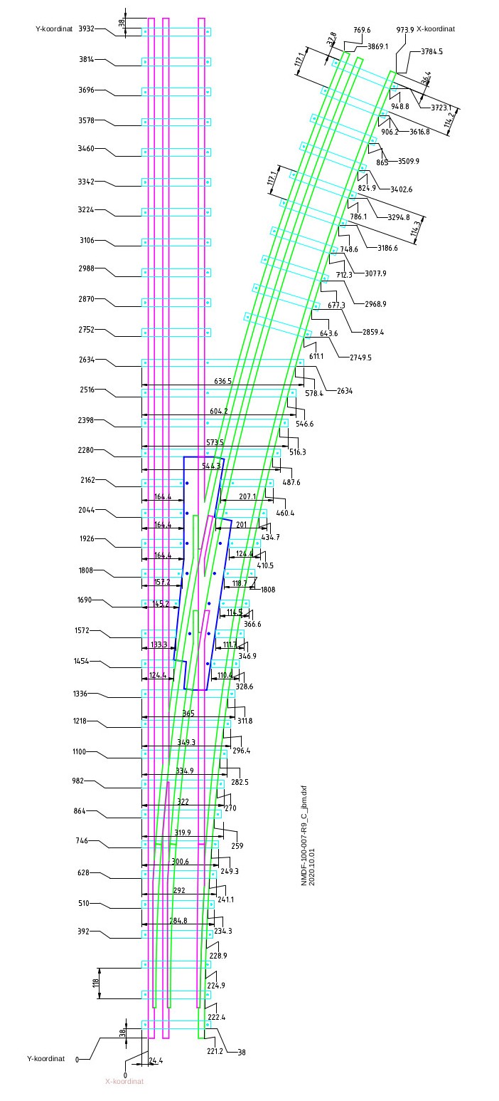
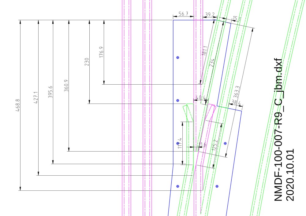
An 0XY coordinate system was defined with origin at one end of the outside straight rail. The drawing below was produced including sufficient of these coordinates to define the positions of the outside straight rail, the inside curved rail and the steel sleepers. A corresponding origin was chosen and marked on the work top. The coordinate points were transferred from the drawing to the work top using an accurate tape measure, a long ruler and a large set square.
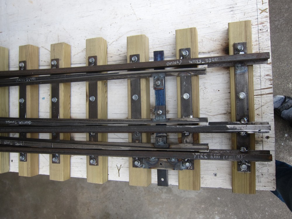
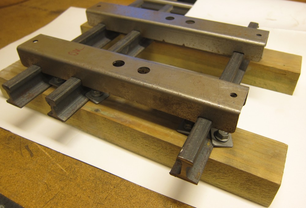
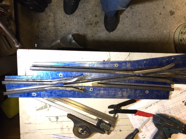
The outside straight rail was located on the work top using a few of these coordinate points and clamped in place. Two additional straight rails were laid parallel to and inside the first rail and accurately located using a large number of rail spacers, of the type shown in the photo below. The outlines of bases of the three straight rails were then traced onto the work top, and the straight rails were removed.
Similarly, the inner curved rail was located on the work top using many of these coordinate points and clamped into place. Two additional curved rails were placed outside and concentric with the inner rail and accurately located using a large number of rail spacers; while also ensuring that their ends coincided with the previous locations of the straight rails, nearest the origin. The outlines of the bases of the curved rails were then traced onto the work top and the curved rails were removed. The steel sleepers and the frog-plate were screwed onto the work top. The surface of the frog-plate was blued and the outlines of the rails were scribed onto the frog-plate in a similar way.
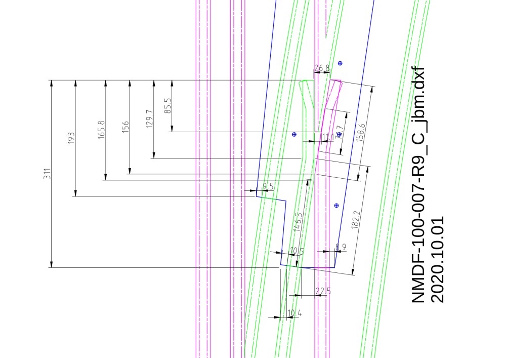
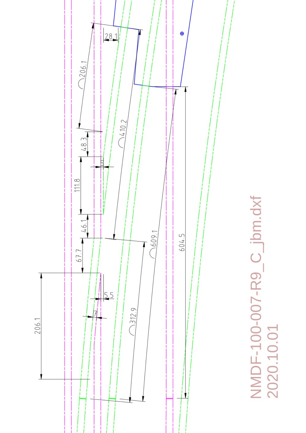
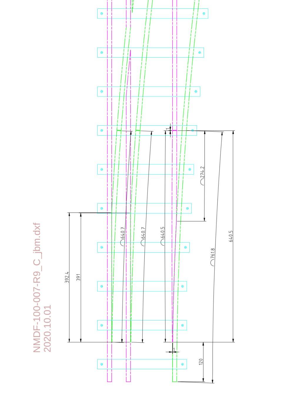
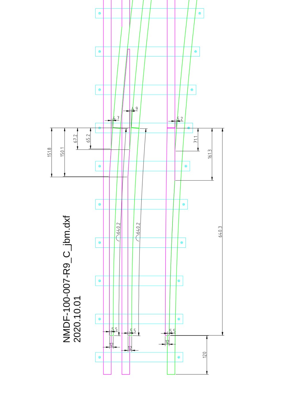
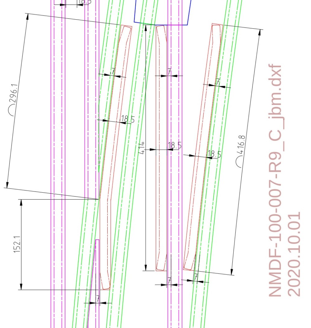
The frog-plate was unscrewed from the work top and my colleague, Jan, took it home to his workshop to manufacture the smaller pieces of crossing rails; i.e. the frogs, and assemble them on the frog-plate. These items were manufactured by cutting pieces from rails and welding them together to make the sharply pointed rail intersections; with the help of liberal use of an angle grinder. The scribed lines on the frog-plate and the following three drawings provided details of the required shapes. In these drawings, continuous lines are used to indicate the bases of the rails and chain-dotted lines indicate the top flanges of the rails; purple for the straight rails and green for the curved rails. The last rail intersection (part 3) is beyond the frog-plate.
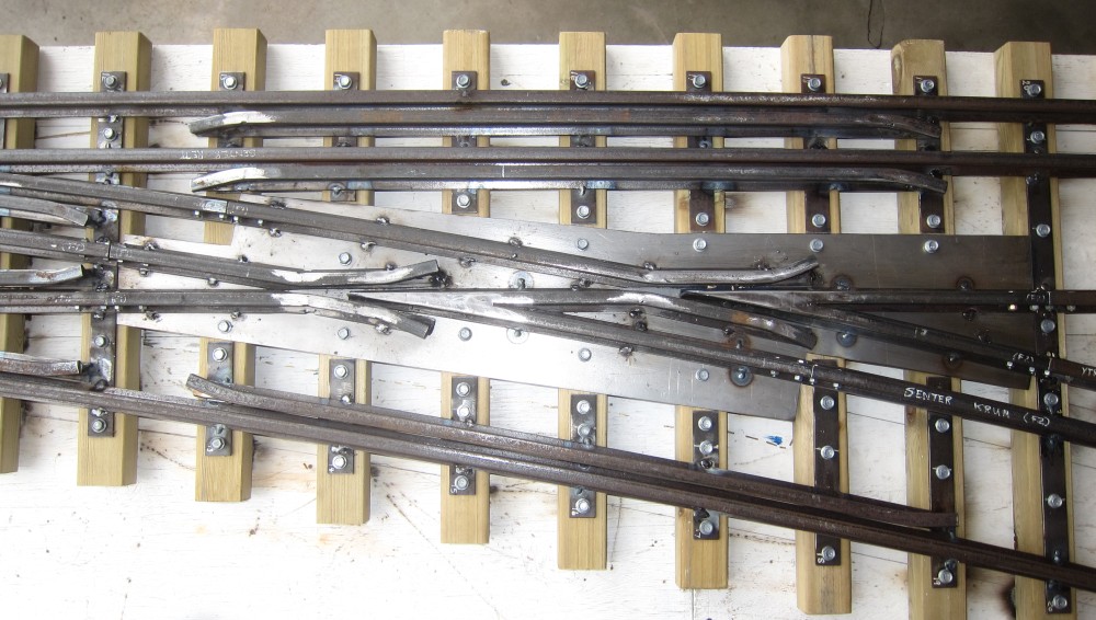
The 4m long rail panels that make up the track are connected by means of fish plates, as shown in the photo below. A gap is allowed for thermal expansion between the panels and the bolt holes in the fish plates are elongated for this purpose. Nylock nuts are used and only lightly screwed down to allow the fish plates to slip relative to the rails. (Both rail ends should ideally be supported vertically to avoid relative vertical motion and oscillating vertical loads on the fish plates as train wheels cross the gap. However, the sleepers are quite close to the gaps.) Fish plates are also used to connect the rails within the points in a fairly similar way, but there is no need to allow for thermal expansion of these short pieces, so the bolt holes are not elongated in these fish plates. Bolt holes are drilled in the ends of the rails, using a locating jig and a pillar drill prior to assembly. The edges of the bottom flanges of the rails are also thoroughly wire-brushed using an angle grinder to remove rust in anticipation of welding.

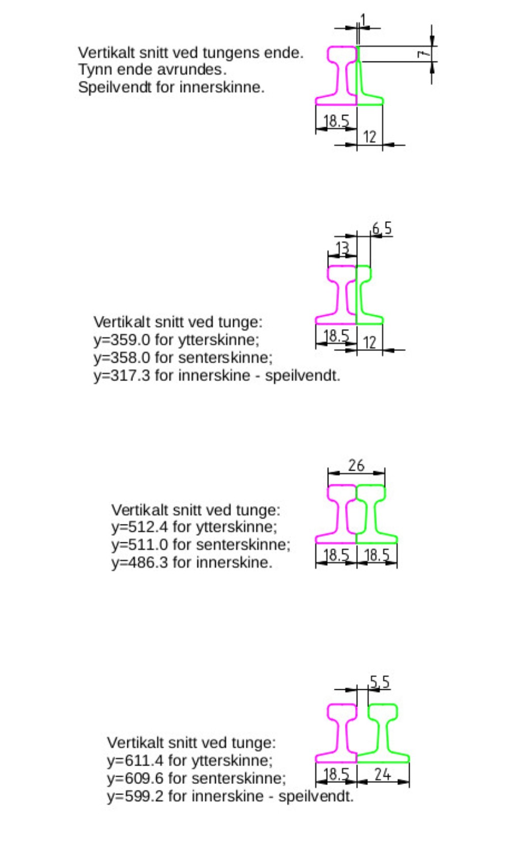
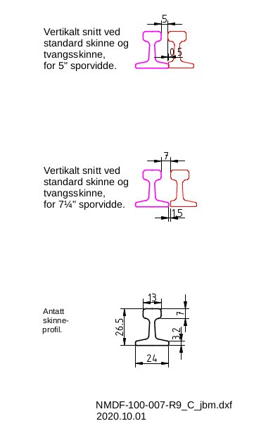
The I-profile of the rails creates a little difficulty in drawing and machining the thin ends of the blades; viz. the hinged parts of the points that can be swung to either side to control which direction a train takes through the points. As initially drawn, thinning down towards the end of the blades could imply no web between the upper and lower flanges of the rails - which would be physically untenable. Some modification to the drawing is needed and achieved by moving the centre point for the construction of each curved blade such that: (a) the centre line is tangential to the rest of the curved rail at the hinged end, and (b) parallel to and offset from the centre line of the straight rail at the thin end of the blade; the offset is half the width of the head of the rail. Similarly, the centre line of the straight blade is also adjusted from the hinge to the thin end. The resulting cross-sections are shown in the drawing below, where the blade is green and the adjacent rail is purple. Part of the foot (or base flange) of the adjacent rail is also cut away to leave room for the blade; i.e. the adjacent side of the foot is cut off at the same width as the head (or top flange) of that rail. Plan views follow below, showing the rail heads and the rail feet in separate drawings. A good deal of trial and error was needed while machining the blades with an angle grinder, in order to obtain an acceptably close fit to the adjacent rails. Ordinary fish plates, with a small gap between the rails, served to provide sufficient flexibility to act as hinges at the hinged ends of the blades.
Rail pieces were initially tack-welded to a few steel sleepers or screwed through the bottom of the frog-plate. After confirming adequate working of the points, all pieces were spot-welded to the steel sleepers or frog-plate. Prior to welding the weld locations on the sleepers were lightly ground with an angle grinder to remove rust and scale, and the dust was removed. Insides and outsides of the rails were alternately welded first to limit weld deformation. I used a TIG-welder, partly for practice, while my colleague, Jan, used a stick welder. The assembly was unscrewed from the work top and it was inverted so that some additional welds could be added on the underside where access was limited from the top. Then the points were placed the right way up again, and wooden sleepers were screwed under the steel sleepers.